Adjustable Frame Screw Instructions
Updated: 18 minutes ago
Tools and Materials
Rectangular block of wood (about 25 mm thick)
Calipers
Set of transfer punches
150 mm ruler
10 mm long drill bit (WNG part #06-5624)
22.2 mm long spade bit (WNG part #06-5622)
14.3 mm long spade bit (WNG part #06-5623)
Butcher’s wax or paraffin wax
Magnetic dial indicator
8 mm T-handle Allen wrench (WNG part #06-5625)
Torque wrench, approx. 11-45 N·m
Wooden dowels
Wood glue
Lag screws and machine bolts (sizes to be determined)
Draw a Detailed Frame Diagram
Before beginning, draw a detailed diagram of the plate. Label each bolt, plate screw, and other relevant location so that measurements can be recorded clearly.
Measure the Frame Height
Before removing the frame from the piano, take precise frame-height measurements. Use a square wooden block taller than the distance from the top of the plate to the top of the case; the top of the case is the reference. Place the block on the plate beside a frame bolt and push it against the case. With your eye level with the top of the case, mark that height on the block. Label each line so it can be matched to the corresponding frame bolt. Repeat for every perimeter plate bolt and for the two plate screws where the case meets the front stretcher. At these two screws, record two reference points: the front stretcher and the side of the case. Keep these measurements if the frame will return to the same position. If possible, identify any area where the plate will be closer than 6.4 mm to the soundboard; the soundboard will need a counterbore there to provide clearance for the lag-screw head.
Determine the Required Bolt Lengths
After removing the plate, measure the plate thickness at every perimeter bolt hole with calipers. Select and record the corresponding bolt code using the table below. Do not assume the plate thickness is uniform: an incorrect bolt length will result in poor plate support.

Plate Thickness Range | Bolt Length | Bolt Code |
8.29 - 30.64mm | 38mm | A |
16.29 - 38.64mm | 46mm | B |
24.29 - 46.64mm | 54mm | C |

Prepare the rim for the lag screws
Plug the original holes with hardwood dowels and trim them flush with the soundboard. Return the plate to its exact final position. Using a transfer punch that matches the diameter of each plate hole, mark the center for every lag screw. It is essential to use the correct transfer punch to obtain the true hole center. Remove the plate and drill the new holes. If plate-to-soundboard clearance is less than 6.4 mm, counterbore for the lag-screw head with a 22 mm spade bit to a depth of 6.4 mm. Then counterbore for the lag-screw shank with a 14.3 mm spade bit: to 38 mm from the soundboard surface if the head counterbore was made, otherwise to 32 mm. Finally, drill with a 10 mm bit to a depth of 105 mm from the soundboard surface. When the parts arrive, verify them before installation. With the plate
outside the piano, test the bolts and lag screws at every perimeter hole. The machine bolt must not bottom out in the lag screw, and at least 13 mm of machine bolt should project below the plate.
Install the Lag Screws
When the plate is ready to go back into the piano, use a 150 mm ruler and a magnetic dial indicator. Lubricate and install all lag screws with butcher’s wax. Turn them down until their heads are about 6.4 mm above the soundboard, or approximately at the height required to support the plate. Place the plate on the lag screws and confirm that all lag-screw heads are accessible through the perimeter bolt holes. If a head does not align, plug and re-drill the hole. If it is very close to center and there is only slight interference, a small enlargement of the plate hole is acceptable.

Set and Secure the Frame Height
Bring the plate to the correct height using the lag screws at the three locations shown in Picture 9. Keep all other lag screws lower so they do not interfere with the adjustment. Use an 8 mm Allen wrench to raise or lower the three lag screws until the recorded height is reached. Install the three corresponding perimeter bolts and tighten to 340 kgf-cm. Place the magnetic base of the dial indicator as close as possible to a lag screw, with a cloth underneath to protect the plate. Position and zero the indicator. Slowly raise the lag screw until the indicator just begins to move; that lag screw is now supporting the plate. Repeat for all remaining lag screws so that they support the plate evenly. Install the remaining perimeter bolts and tighten them to 340 kgf-cm.
Warning: Do not tighten the perimeter bolts beyond 340 kgf-cm.

Completion
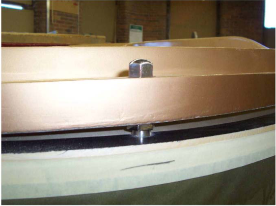
The Adjustable Plate System is now complete. This photo shows the finished installation inside the piano; the photograph was taken with the outer rim removed: